

nxLimit
nxLimit holds your NeXus particle attributes within set bounds, capping velocity, position, scale, rotation, speed, radius, mass or a user value. It works as a stack of layers, so you can combine several limits and blend them together.
Add it from Add ▸ INSYDIUM NeXus ▸ nxLimit. It arrives as an empty. Add one or more layers, set each to the attribute it limits, then blend them. All of its settings live in Properties ▸ Physics.
A stream of particles born at mixed speeds, held to a single top speed by a Speed limit, so the flow evens out instead of the fastest particles racing ahead.
Object Properties
Section titled “Object Properties”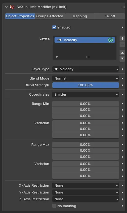
The nxLimit panel in Properties ▸ Physics, on the Object Properties tab, showing a Velocity layer.
Enabled
Section titled “Enabled”Turns nxLimit on or off. Disable it to switch off its limits without deleting it.
Layers
Section titled “Layers”The stack of limit layers. Use the + button to add a layer, choosing which attribute it limits from the menu that appears, and the - button to remove the selected one. Each layer has an enable toggle on the right of its row, so you can switch a layer on or off without removing it.
Layers are processed from the top of the stack down, each blending with the result of the layers above it. Select a layer to show its settings underneath.
Layer Settings
Section titled “Layer Settings”These settings apply to the layer selected in the Layers list. The top block is shared by every layer. The controls below it change with the Layer Type.
Layer Type
Section titled “Layer Type”Sets the attribute this layer limits. A new nxLimit starts with a Velocity layer. The options are Velocity, Position, Scale, Rotation, Speed, Radius, Mass and User Value, each described below.
Blend Mode
Section titled “Blend Mode”Sets how this layer combines with the layers above it. Set as Normal, by default. The other options are Add, Subtract, Multiply, Difference, Screen, Overlay, Min and Max.
Blend Strength
Section titled “Blend Strength”Sets how strongly this layer contributes to the blend. Defaults to 100%.
Velocity
Section titled “Velocity”Limits each particle’s velocity per axis, as a percentage. Its layer panel is the one shown in the Object Properties panel above.
Coordinates
Section titled “Coordinates”Sets the space the velocity limits are measured in. Set as Emitter, by default. The other options are World and Custom Object. When set to Custom Object an Object field appears, to measure relative to a chosen object.
Range Min
Section titled “Range Min”The lowest velocity allowed on each of the X, Y and Z axes, with a Variation for a per-particle spread.
Range Max
Section titled “Range Max”The highest velocity allowed on each axis, with its own Variation.
X-Axis Restriction / Y-Axis Restriction / Z-Axis Restriction
Section titled “X-Axis Restriction / Y-Axis Restriction / Z-Axis Restriction”Sets which direction each axis is restricted in. Each is set to None, by default. The other options restrict the positive or the negative direction of that axis.
No Banking
Section titled “No Banking”Stops the velocity limit from banking the particles as they turn. Off by default.
Position
Section titled “Position”Limits where each particle can travel, per axis.
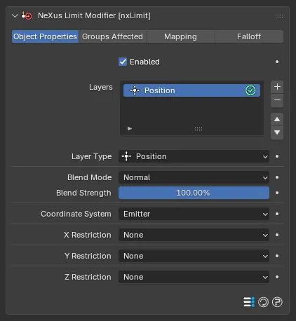
The Position layer settings, with each axis restriction set to None.
Coordinate System
Section titled “Coordinate System”Sets the space the position limits are measured in. Set as Emitter, by default. The other options are World, Particle and Custom Object, the last of which reveals an Object field.
X Restriction / Y Restriction / Z Restriction
Section titled “X Restriction / Y Restriction / Z Restriction”Sets how each axis is limited. Each is set to None, by default. The other options are X+ (or Y+, Z+), X-, Range and Fixed.
Depending on the option, a minimum, maximum or fixed position value appears for that axis, with a Variation on the minimum and maximum.
Limits each particle’s scale, per axis.
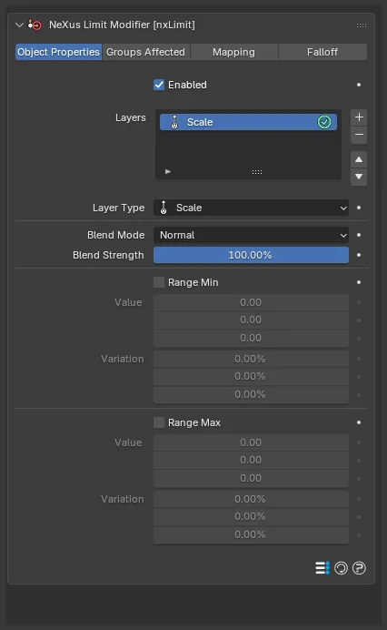
The Scale layer settings, with Range Min and Range Max off by default.
Range Min
Section titled “Range Min”Enable it to set a lower scale limit, in the Value fields for each axis, with a Variation. Off by default.
Range Max
Section titled “Range Max”Enable it to set an upper scale limit, with its own Value and Variation. Off by default.
Rotation
Section titled “Rotation”Limits how far each particle can rotate.
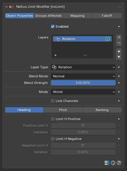
The Rotation layer settings, on the Heading channel tab with Link Channels off.
Sets the space the rotation limits are measured in. Set as World, by default. The alternative is Relative.
Link Channels
Section titled “Link Channels”When on, one set of limits applies to all rotation channels together. When off, you set the Heading, Pitch and Banking channels separately, each on its own tab. Off by default.
Each channel has a positive and a negative limit, which you enable and set in degrees, each with its own Variation.
Limits each particle’s overall speed.
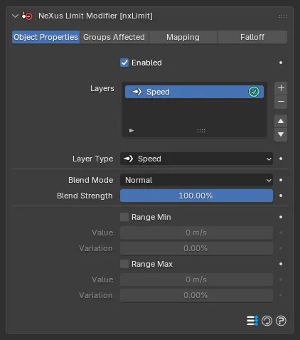
The Speed layer settings. Radius, Mass and User Value share this same layout.
Range Min
Section titled “Range Min”Enable it to hold the speed above a floor, set in the Value field, with a Variation. Off by default.
Range Max
Section titled “Range Max”Enable it to hold the speed below a ceiling, set in the Value field, with a Variation. Off by default.
2 m/s
8 m/s
The Range Max speed cap is 2 m/s, on the left, and 8 m/s, on the right, for a stream born at mixed speeds. A low cap holds every particle to a slow, even crawl. A high cap lets the faster particles race ahead.
Radius
Section titled “Radius”Limits each particle’s radius, with the same Range Min and Range Max controls as Speed, applied to the particle radius. Its layer panel is identical to Speed, shown above.
Limits each particle’s mass, with the same Range Min and Range Max controls as Speed, applied to the particle mass. Its layer panel is identical to Speed, shown above.
User Value
Section titled “User Value”Limits each particle’s user value, with the same Range Min and Range Max controls as Speed, applied to the particle’s user value. Its layer panel is identical to Speed, shown above.
Groups Affected
Section titled “Groups Affected”Use the Groups Affected tab to restrict nxLimit to particles in specific nxGroup groups, rather than affecting every particle.
Mapping
Section titled “Mapping”Use the Mapping tab to drive nxLimit’s settings from particle data instead of fixed values, so a particle’s own attributes can change the limits it feels. See Mapping for how this works.
Falloff
Section titled “Falloff”Use the Falloff tab to limit where nxLimit acts. Add one or more nxFalloff objects to the list and blend them, so the limits only affect particles inside the falloff region.
Copyright © 2026 INSYDIUM LTD. All Rights Reserved.